Welcome to ExamNotes for Network Plus N10-007 Objective 3.1. This installment deals with the required documentation you are expected to generate for optimal network management.
In order to function properly, every organization will have standard operating procedures and policy documentation governing all aspects of the operation. This documentation will vary from one organization to another in specifics, but will all cover the network configuration, special instructions and contact information of administrators and vendors.
There will also be detailed floor plans indicating the physical locations of all hardware covering everything from devices like switches, routers and Telco closets (IDF/MDF) to the water and power cutoffs. This information will also include the manufacturer, device type and asset tracking information.
Your instructions should be vetted by management to ensure that there are no negative events caused by your activity.
There will always be changes to your network like hardware, installations, upgrades and software patches. In a well-structured environment, any moves adds or changes to the network will be documented. When any change is necessary you must be sure that anything you do is documented and that there is a fallback procedure to the “last known good” in the event of problems with the latest change.
There are two ways to document your network topology. A logical diagram provides a broad illustration of the network configuration from a high level. The logical diagram will include the entire WAN layout as opposed to the routers and other devices involved. When more detail is required you will use a physical map. The physical map will show the components of your network and the connections used.

Logical Network Diagram
When working with either logical or physical diagrams there are standard network symbols that are used to identify the devices used on the network. These symbols allow you to demonstrate the network topology to a third party. Cisco makes these symbols available for free. Depending on the mapping software you may see them colorized.
Here are a few:
Icon | Device |
Router | |
Switch | |
Firewall | |
Workstation | |
Laptop | |
Cell Phone | |
Printer |
Every network connection from the wall jack to the IDF/MDF will be clearly labeled. Your routers, switches, and servers will be mounted in a rack in the IDF/MDF closet (room). The wiring and port location information for each connection will be labeled on the switch. The available space for this label is small and will usually be coded. The cables should be tagged with similar coded information containing the floor of the building, office or area where the destination jack is located. In addition to the coded tag, the cables may also be color-coded and barcoded based on their application. Here is an actual rack containing a router, switches and patch panels.
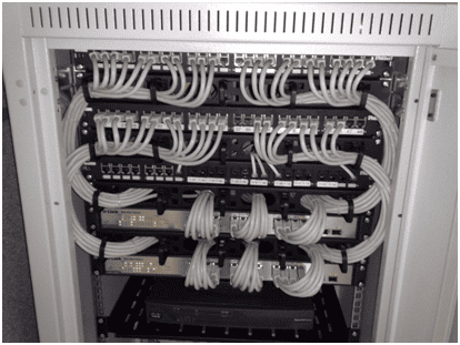
In the rack diagram section above we described how the devices and cables are labeled. This labeling must be documented. The documentation enables technicians to quickly understand the cable purpose and the location it serves.
We have established the network configuration using logical and physical diagrams. An important method of analyzing your network’s performance is by using a performance baseline. Once established the baseline allows you to compare your current performance metrics like throughput and response time against those of the baseline. Baselines allow you to analyze your network’s performance against previous baselines. Your network will experience higher demand based on the time of day, day of the week or even longer periods. Knowing your network utilization will help you spot problems or plan for events that will increase demand.
Inventory management encompasses all the company’s assets. Inventory management software is used to keep track of the assets and their locations. From the demarc to the workstation each device (asset) should be recorded by the manufacturer, model number, date of acquisition and its location. This includes the CSU/ DSU, routers, switches, servers, and even cables. Many companies use asset tags with barcodes to identify the asset. RFID tags are prevalent in asset identification plans.
That’s all for objective 3.1! See you in 3.2!