Welcome to our free Network+ study guide! This edition will focus on network cabling types starting with their physical properties. Following that we’ll explain the connector types and devices used for interconnection. Lastly, we’ll look at the Standards that apply to each type. We will try to present the information logically as it pertains to each cable or connector type. Dig in!
Coaxial cable is considered a legacy network cable, but you will still find it in cable TV installations. For networks, it has been replaced by twisted pair and fiber optic cables. Knowledge of the Coaxial cable and connectors is still required by the CompTIA Network+ objectives. So know the copper cables and their connectors.
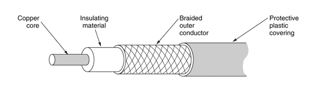
Coaxial Cable
Compare the Unshielded Twisted Pair (UTP) cable to the Shielded Twisted Pair (STP) cable. The difference between the two cable types is in the internal construction of the cable, specifically the amount of insulation or shielding surrounding each internal cable pair. Each internal pair is twisted using a specified number of twists per inch. This reduces the possibility of the pairs being parallel to each other and prevents crosstalk.

Safety is your number one concern when running network cabling. This concerns not only the usual such as dangling cables or running too close to power lines, but also the materials you are using. The construction of the network cable you are running is something you may not consider, but when examining cables you will find that the outer sheath generally consists of one or two types of material, PVC (PolyVinylChloride) or Plenum grade. Incorrect usage of these two types could result in you having to rewire your entire installation. PVC is cheaper and is perfectly suitable for patch cables and exposed wiring, but once you run inside a dropped ceiling or any location that moves air, plenum grade cabling is required by most states. PVC releases toxic fumes when ignited and it is easily combustible. Plenum cable is less flammable than PVC and mandatory wherever ventilation is present. Plenum cable will be clearly marked.
If the incorrect cable is used, the entire installation must be rewired.
Fiber optic transmissions use pulses of light for signaling which are then sent over plastic or glass strands. The glass medium (fiber) is susceptible to breakage and signal loss if it is bent over a certain radius which is dependent on the thickness of the fiber. Fiber optic cable should never be coiled tightly.
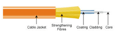
Fiber detail
The fiber core is protected using a plastic sheath wrapped in synthetic strength fibers, which give the cable resistance to breakage. A plastic outer sheath completes the wire. If there is any concern about moisture seeping into the cable, a synthetic gel is used to fill any gaps and protect the fiber core from moisture. A plastic outer sheath encases the rest of the wire.
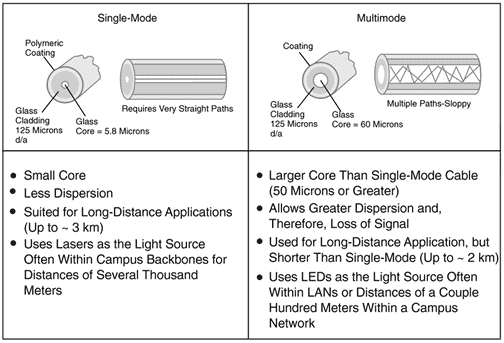
Single-mode/Multimode
Single-Mode Fiber (SMF) cable provides the highest bandwidth and longest transmission distance compared to multimode fiber (MMF). SMF uses a very small core and a laser light source, making it best suited for longer distance backbone connections. SMF is less tolerant to bending and is more expensive than MMF.
MMF can use an LED light source and MMF has a considerably larger core that supports multiple signal paths. MMF is generally used for shorter distances (up to <) and is less expensive than SMF.
Let’s review the copper connector types used with each cable standard, starting with fiber connectors. As always, the goal is to obtain maximum performance with minimal signal loss.
All fiber connections have a small air gap in the fiber termination. Initially, fiber ends were more squared off and prone to some signal loss. Today, fiber ends have evolved into the Physical Contact Connector (PCC) which polishes the cable ends and reduces signal loss.
Ultra Physical Contact Connectors (UPC) possess a finer polish on the fiber PCC connection, allowing for more reliable signaling with even smaller loss.
The APC (Angled Physical Contact Connector) is used in installations where no more than 0.0001% Optical Return Loss (ORL) is tolerated. This is achieved using an 8-degree angled cable end, making the air gap more diagonal which allows for tighter connections.
Let’s now discuss the connector types. Here are the connector types you’ll need to know.
ST- The ST (Straight Tip) connector is one of the longstanding connector types. This should be easily recognizable at first glance.

ST Fiber Connector
When identifying an ST connector, look out for the BNC-type connector and the straight tip on the fiber.
SC- The SC (Subscriber Connector) has also been in use for a while and is a very reliable snap-in connector that is easy to use and has low signal loss. This connector may sometimes be referred to as a standard connector or a square connector due to its shape. The ST and SC connectors have a larger form factor than the Mechanical Transfer Registered Jack (MT-RJ) and the LC connector.

SC Fiber Connector
LC- The LC connector is a newer design relative to the others and may be referred to as a Local connector, Lucent connector, or even a Little connector. The main advantage of the LC connector is its size since the connector is about half the size of the SC connector. Both connectors are completely comparable otherwise.
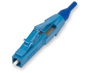
LC Fiber Connector
A transceiver is used to convert fiber MMF or SMF cable signals for use on an Ethernet network in fiber-to-premise installations. For large scale applications, a switch is used instead to convert the fiber signals.
The first transceiver developed for this purpose was the Gigabit interface converter (GBIC), capable of supporting RJ-45 or SC connections. This device is now obsolete and newer devices have become more popular.
The small form-factor pluggable (SFP) transceiver, aka mini GBIC, has the same capabilities as the GBIC while taking up less space. Generally used in 1 Gbps connections, mini GBICs are rated up to 5 Gbps.
SFP+ transceivers are now capable of 16 Gbps.
Quad small form-factor pluggable transceivers (QSFP) support data rates of up to 40 Gbps through the use of four channels, each supporting 1 Gbps, on a single transceiver. This is codified in the IEEE 802.3ba standard.
provides additional bandwidth, when compared to QSPF, by supporting four channels at 10 Gbps per channel.
At least one Intermediate distribution frame (IDF) or punchdown block can be found in the network or telco closet whenever copper cabling needs to be interconnected. IDFs come in two types, the 66 block and the 110 block. IDFs are called punchdown blocks because of the way the wires are connected. First, wires are placed in each pin on the block. Next, the wires are seated properly and then connected using a punchdown tool. Lastly, the excess wire is cut off.
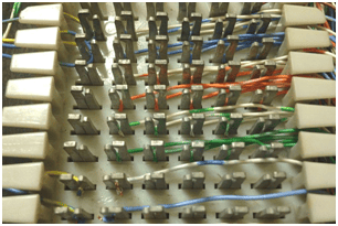
Punchdown Block
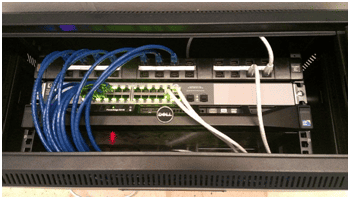
Ethernet deployments require a method to distribute the signal. Usually, a switch will be connected to a port on a patch panel. The patch panel distributes traffic to workstations or other switches. In the image below, a 24-port patch panel is shown at the top of the image, a 24-port network switch is shown in the middle, and the server is shown on the bottom.
CAT3 – Popular in the early days, this twisted pair implementation type uses up to six wires or conductors. CAT3 was most commonly used in wired telephones where two pairs were used for each phone connection. This means the cable itself can support two phone lines. Shown below is a comparison of a two-pair RJ-11 connector, used in CAT3, alongside an eight-pin RJ-45. This is clearly legacy technology. The reason CompTIA keeps this (and other items considered outdated) in the exam objectives is that when supporting existing systems we will on occasion stumble into these older technologies.

CAT5 – Getting harder to find and no longer installed, this cable rating uses four pairs and can support up to 100Mbps transmission speeds with a maximum cable length of 100 meters (328 feet). You can get higher speeds in real-world applications but for the purpose of Network+, memorize the specification described here. CAT5 uses RJ-45 connectors.
CAT5e – This cable is known as CAT5 Enhanced where the enhancement refers to reduced crosstalk. This doesn’t sound like a big deal until you look at the speed improvement. How does 10 times faster sound? CAT5e supports gigabit ethernet (1000Mbps)! This can be attributed to a stricter attention to the number of twists per inch in the pairs. Remember, your hardware has to support the speed. It’s not a magic cable. CAT5e supports 1Gbps with a maximum cable length of 90 meters (295 feet). Cat5e uses RJ-45 connectors.
CAT6 – With CAT6 we are coming out of legacy. It supports 10Gbps at a frequency of 250 Mhz. These speeds can be attributed to a further reduction in crosstalk. While maintaining the same external RJ-45 form, the connector and cable are engineered to further isolate the cables from each other, resulting in higher throughput.

CAT6 RJ-45
The wires are arranged in the connector to allow a slight, yet significant separation compared with CAT5 wires, which run straight, horizontal, and adjacent to each other. As you know, parallel cables will practically guarantee crosstalk. The maximum length for a CAT6 is 90 meters with an additional 10 meters for a patch cable. Cat6 uses RJ-45 connectors.
CAT6e – This enhancement doubles the transmission frequency to 500 MHz and restores the traditional segment length to 100 meters (328 feet). This is technically not a standard but CAT6e is widely recognized and observed. Cat6e uses RJ-45 connectors.
CAT7 – This performance standard increases the transmission frequency to 600 MHz and provides a more reliable and durable cable than its predecessors. CAT7 wraps the entire insulated pair with an additional layer, wrapping the whole cable bundle to provide an additional layer of shielding. Cat7 uses RJ-45 connectors.
CAT8 – The transmission capability of CAT8 is dramatically increased to 2Ghz, allowing a maximum data rate of up to 40Gbps using individual wire insulation and foil/braided shielding. CAT8 uses the standard RJ-45 connector and utilizes all four wire pairs.
“RJ-45 This connector succeeded the RJ-11 for network use. It uses four twisted pairs of wire in a configuration that reduces crosstalk and other cable-related issues. RJ-45 was capable of matching RJ-11 speeds (10Mbps) in its initial configuration. Please review the T-568 A and T-568 B wiring pinouts below which indicate how RJ-45 connectors were wired.

The TIA and EIA standards are the same for the configuration with the TIA being more widely used. A cable that is terminated identically at both ends as T-568b or T-568a is called a straight-through cable and is used to connect computers to devices like hubs, switches, and routers. The transmitting pair of wires on the PC will be received on the device. This is the most common RJ-45 Ethernet termination. When PC to PC connections are directly connected to each other a crossover cable is used. The crossover cable uses T-568a termination on one end and T-568b on the other this switches the send/receive pairs and enables the connection.
You will encounter two types of coaxial cables in the environment as follows:
Your objectives call for knowledge of the F-Type connector. This is not as much a network connector as it is video. Your Home Media Center PC will require this connector to connect your cable or antenna system to the PC.
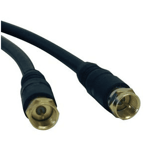
F Type
Using RG-6 cable the connection for this is an F-type connector. It is similar to BNC with the difference being that the F connector screws onto the component using multiple rotations of the connector to the unit creating a connection that is more likely fail in the cable than it is at the connection point. The connection is strong and extremely unlikely to pull out.
Thinnet or RG-59 cabling is largely obsolete, but you never know…
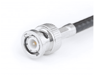
RG 59 Coaxial
This 10BASE2 connector and cable were harder to manage than its 10BASET cousin. It used BNC connectors and a somewhat less manageable shielded copper core cable. It matched the 10Mbps speed and had a longer range but it was difficult to implement the required bus topology and needed a T connection at each host along with termination at the cable ends to prevent signal reflection.
Twinax
The Twinax cable contains two internal conductors (hence the name) as opposed to a single-core Coaxial cable. allowing the connection to be polarized. This prevents mixed signals ensuring signal integrity.
100BaseT is deployed over CAT5 (or better) cabling using RJ-45 connectors terminated using the TIA-568 A or TIA-568 B standard. This is called Fast Ethernet and supports speeds up to 100Mbps.
100BaseTX is similar to 10BaseT and is also deployed over CAT5 (or better) cable. 100BaseTX supports duplex connections via two wire-pairs, one for sending and the other for receiving.
1000BaseT is called Gigabit Ethernet and supports speeds up to 1Gbps. It is deployed over CAT5 (or better) cabling using RJ-45 connectors terminated using the TIA-568 A or TIA-568 B standard. 1000BaseT uses all four wire pairs.
10GBaseT is deployed over CAT6 (or better) cabling using RJ-45 connectors terminated using the TIA-568 A or TIA-568 B standard. 10GBaseT is called 10-Gigabit Ethernet and supports speeds up to 10Gbps.
40GBase-T is called 40-Gigabit Ethernet and supports speeds up to 40Gbps. It is deployed over CAT6a (or better) cabling using RJ-45 connectors terminated using the TIA-568 A or TIA-568 B standard.
Fiber
100Base-FX was developed in the 1990s and is still used today because it supports the longest segment length of up to two kilometers.
100Base-SX is a lower-cost implementation of Fast Ethernet over fiber. It uses LEDs instead of lasers as a light source and has a shorter wavelength over shorter distances when compared to 100Base-FX.
1000BaseLX uses SMF or MMF fiber connections and is comparable to Gigabit Ethernet. Termination is based on fiber type and wavelength.
1000BaseSX uses different modulation techniques over MMF and has a shorter range. Termination is based on fiber type and wavelength.
supports transmissions of up to 30 meters over single-mode fiber at full 10Gbps speed.
10GBase-LR supports transmissions of up to 10 kilometers over single mode fiber at full 10Gbps speed. LR stands for long range.
Coarse wavelength division multiplexing (CWDM) uses multiplexers to reduce cost while providing between 4 and 18 channels per
Dense wavelength division multiplexing (DWDM) supports up to 320 channels and is amplified on WAN links along the route. DWDM is typically used for high-bandwidth connections such as those between an ISP and the Network Service Provider (NSP).
Bidirectional wavelength division multiplexing (WDM) defines the simultaneous transmission of optical channels on fiber that can propagate in opposite directions.
Well, that’s it for 1.3! We hope it was helpful. See you in 1.4!